The low-voltage reactive power compensation device is suitable for automatic reactive power compensation in the 50Hz, 0.4kV urban distribution network. It adopts a series of relatively practical technologies and high-quality components, integrating reactive power compensation and grid monitoring. It not only compensates for reactive power loss in the grid, improves the power factor, reduces line loss, thereby enhancing the load capacity and power supply quality of the grid; but also can monitor the three-phase voltage, current, power factor and other operating data of the grid in real time. It can complete comprehensive management such as monitoring, analysis processing, and report output for the entire low-voltage distribution line, providing first-hand data for the scientific management of low-voltage distribution lines.
1. Device Overview
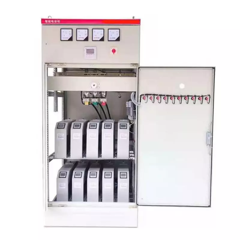
The device mainly consists of a box, a comprehensive power distribution and measurement control instrument, a composite switch, capacitors, a single group capacitor protection device, a lightning arrester, a main power supply switch, sampling and measurement transformers, indicator lights for the operating status of the capacitor group, etc. The main functional features are as follows:
◆ The device is made of steel plate with powder coating treatment, presenting an elegant and durable appearance, resistant to aging and corrosion, with a long service life;
◆ The structural design is compact and reasonable, with neat wiring, convenient maintenance, and a perfect combination of heat dissipation and sealing measures;
◆ It can adopt various compensation schemes such as coded, full △, full Y or △ + Y, combining fixed compensation, static compensation, and dynamic compensation, with economic cost and good compensation effect;
◆ It uses intelligent composite switches, without switching surge current and no need for heat dissipation, and will not generate harmonic injection, with high reliability;
◆ It has protection functions such as overvoltage, undervoltage, phase loss, harmonic over-limit, overload, and circuit break;
◆ It has data monitoring and statistical functions such as voltage monitoring, load monitoring, harmonic monitoring, and energy accumulation;
◆ It has RS232/485 communication interfaces, and can adopt wired, wireless, meter reader, GPRS/CDMA, etc. communication methods;
◆ It has standalone or network version background management software, for data statistics, analysis, graphic display, and report printing;
All electrical components in the device comply with corresponding national standards or industry standards, and strictly follow the following standards:
GB191-1990 Packaging and Storage Symbol Marking
GB/T2681-1981 Color of Wires in Electrical Apparatus Sets
GB/T4942.2-1993 Protection Grade of Low Voltage Electrical Appliances
GB/T9466-1989 Basic Test Methods for Low Voltage Enclosed Switchgear
GB12325-1990 Power Quality, Allowed Deviation of Supply Voltage
GB12747-1991 Self-healing Low Voltage Parallel Capacitors
GB/T14594-1993 Harmonics of Public Power Grid
GB/T15576-1995 General Technical Conditions for Low Voltage Reactive Power Static Compensation Devices
DL/T721-2000 Remote Terminal of Distribution Network Automation System
DL/T842-2003 Operating Technical Conditions for Low Voltage Parallel Capacitor Devices
DL/T597-1996 Ordering Technical Conditions for Low Voltage Reactive Power Automatic Compensation Controller
JB7113-1993 Low Voltage Parallel Capacitor Devices
2. Operating Conditions
Environmental Temperature: Not higher than +55℃, not lower than -25℃, and the 24-hour average temperature should not exceed +35℃;
Relative Humidity: At a temperature of +25℃, it should be ≥ 90%;
Altitude: The altitude should not exceed 2000m;
Working Environment: The surrounding medium should be non-flammable, non-explosive, free of conductive dust, and free of media that could damage insulation;
Installation Location: There should be no severe vibration or jolting, and the installation tilt should not exceed 5%;
Voltage Fluctuation Range: Not exceeding ±15% of the rated working voltage.
3. Technical Specifications
1. Rated Voltage: 0.23kV / 0.4kV; Rated Frequency: 50Hz;
2. Rated Compensation Capacity: 30, 45, 60, 75, 90, 105, 120, 150, 180, 240, 300, 360 kvar;
3. Rated Current: 43A, 65A, 87A, 109A, 131A, 142A, 174A, 218A, 260A, 348A, 435A, 522A;
4. Compensation Mode: Phase-by-phase compensation, three-phase compensation or mixed phase-by-phase + three-phase compensation;
5. Switching Mode: Code-based switching, equal-capacity switching or arbitrary code;
6. Protection Mode: Equipped with overvoltage, undervoltage, phase loss, harmonic over-limit, overload, short circuit and other protection functions;
7. Control Physical Quantity: Using reactive power, power factor and voltage as verification conditions;
8. Sensitivity: < 100mA;
9. Measurement Accuracy: Voltage and current 0.5 class, power factor, reactive power, active power 1.0 class;
10. Average Fault-Free Time: MTBF ≥ 40,000 hours
11. Dielectric Strength: Main circuit phase-to-phase and earth 2500V, lasting 1min; auxiliary circuit earth 2000V, 1min.
4. Application Fields
The low-voltage reactive power compensation device is controlled by an intelligent controller to dynamically switch on/off the thyristor filter. It integrates the removal of grid harmonics, reactive power compensation, and power quality monitoring. It can remove grid harmonics to meet national standards, real-time compensate for reactive power losses in the grid, improve power factor, reduce line losses, thereby enhancing the load capacity and power supply quality of the grid. At the same time, it can also monitor real-time the three-phase voltage, current, frequency, active power, reactive power, power factor, harmonics, etc. of the grid operation data, making it suitable for scenarios with high harmonic content in the load, low power factor, and large load fluctuations. The device has complete protection measures such as overvoltage, undervoltage, phase loss, overcurrent, short circuit, transient overvoltage, sound and light alarms, etc., and there are no issues of reactive power reverse transmission or harmonic amplification.
Main technical parameters:
Rated voltage: 0.4 - 1 kV;
Rated capacity: 30 - 360 kvar (depending on specific circumstances)
It can quickly perform dynamic compensation according to the changes in system reactive power, improving the power factor;
Filter out harmonic currents;
Response time is fast (20 - 40 ms);
The capacitors are grouped and switched on and off, causing little impact on the system during the switching process;
The entire device provides comprehensive protection functions, ensuring safety and reliability.
Main application fields: The device can quickly compensate for reactive power and effectively filter out harmonics. It can minimize the harm caused by harmonic sources and improve power quality while fully utilizing system capacity. Typical applicable loads include the following types of harmonic sources.
(1) AC/DC transmission motors and rolling mills
When the grid voltage fluctuates and the power factor decreases, odd-order harmonics are generated, causing distortion in the grid voltage.
(2) Welding machines
When the welding machine is a single-phase load, the 3rd harmonic current is large, the waveform is severely distorted, the three-phase current is extremely unbalanced, and the voltage flicker is severe.
(3) Intelligent buildings
In the power distribution of commercial buildings and high-rise residences, modern power electronic equipment (variable-speed motors, air conditioners, online UPS, switching power supplies, color TVs, laser printers, etc.) are nonlinear loads. Although the load is less impulse-like, the generated harmonic current is very serious.
(4) Arc furnaces
Arc furnaces, as nonlinear and impulse loads connected to the grid, cause severe three-phase imbalance in the grid, generate negative sequence currents; produce high-order harmonics, with the coexistence of even-order and odd-order harmonics being common, making the voltage distortion more complex; there is severe voltage flicker; and the power factor is low.
(5) Medium-frequency furnaces
The odd-order harmonic currents generated by medium-frequency furnaces during operation are severe.