The dual-power automatic transfer device, as the name suggests, automatically connects to the backup power source through the dual-power switching switch when the main power supply suddenly fails, ensuring that our operation does not stop and can continue. The purpose of the dual-power automatic transfer switch is simply to have one power source in use and another as a backup. When the main power supply suddenly fails or experiences a power outage, through the dual-power switching switch, it automatically transfers to the backup power source, allowing the equipment to continue operating normally.
1. Introduction
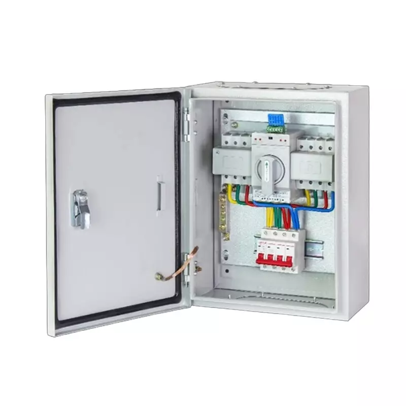
The dual power automatic transfer device (hereinafter referred to as the transfer device) is composed of one or several transfer switches and other necessary electrical components. It is an electrical appliance used to detect the power circuits and automatically switch one or more load circuits from one power source to another. It is a dual power automatic transfer switch with perfect performance, high safety and reliability, high automation level, and wide application range. This type of switch is widely used in many places in our lives, and is found in many companies and residential areas.
The electrical appliances of the dual power automatic switching device are mainly used in emergency power supply systems. They are switches that automatically switch the load circuits from one power source to another (backup) power source to ensure the continuous and reliable operation of important loads. Therefore, they are often applied in important power consumption places, and the reliability of their products is particularly important.
2. Dual Power Supply Operating Procedures
1. In case of power outage and if power cannot be restored within a short period of time, the backup power supply must be activated.
Steps:
① Cut off the circuit breakers for the mains power supply (including those in the distribution room control cabinet and the dual power supply switchgear for mains power supply), and pull the double-pole anti-backfeeding switch to the backup power supply side. Keep the circuit breaker for the self-provided power supply in the dual power supply switchgear in the closed state.
② Start the backup power supply (diesel generator set). Once the generator set is running normally, sequentially close the air switches for the generator and the circuit breakers in the self-provided power supply control cabinet.
③ Sequentially close the circuit breakers for each backup power supply in the power switchgear, and supply power to each load.
④ During the operation of the backup power supply, the on-duty operator must not leave the generator set and should adjust the voltage, plant frequency, etc. in a timely manner according to the changes in the load. Address any abnormalities promptly.
2. When the mains power supply is restored, promptly complete the power conversion work, cut off the backup power supply, and restore the mains power supply.
Steps:
① Sequentially and in order, disconnect the circuit breakers for the self-provided power supply. The sequence is: the circuit breaker for the self-provided power supply in the dual power supply switchgear → the circuit breakers in the self-provided power supply distribution cabinet → the main switch for the generator → set the double-pole switch to the mains power supply side.
② Shut down the diesel engine according to the shutdown steps.
③ Sequentially, close the circuit breakers from the main switch for mains power supply to each branch switch, and place the circuit breaker for the self-provided power supply in the dual power supply switchgear in the closed position.
3. Performance
1. It adopts dual-row composite contacts, horizontal connection mechanism, micro-motor pre-storage and micro-electronic control technology, basically achieving zero arcing (without arc suppression cover);
2. It employs reliable mechanical interlock and electrical interlock technologies;
3. It adopts zero-crossing position technology;
4. It has obvious on-off position indication and lock function, reliably achieving isolation between the power supply and the load, with high reliability and a service life of over 8,000 times;
5. It is an integrated mechanical and electrical design, with accurate, flexible and reliable switch conversion, good electromagnetic compatibility, strong anti-interference ability, no external interference, and high automation program;
6. The fully automatic type does not require any external control components.
7. The intelligent controller uses a single-chip microcomputer as the control core, with simple hardware, powerful functions, convenient expansion, and high reliability.
8. It has short-circuit, overload protection functions, overvoltage, undervoltage, and phase loss automatic conversion functions, and intelligent alarm functions.
9. The automatic conversion parameters can be freely set externally.
10. It has an intelligent protection function for the operating motor.
11. It has a computer networking interface for the purpose of realizing remote control, remote adjustment, remote signaling, and remote measurement functions.